
Removing and installing drive shaft with triple roller joint AAR 3300i (with external splines for insertion in gearbox) — AUDI
Removing and installing drive shaft with triple roller joint AAR 3300i (with external splines for insertion in gearbox) on Audi: 31 steps.
Front drive shaft out and in on the TT Mk2 (8J) with the AAR 3300i triple roller joint that plugs straight into the gearbox on external splines. The hub bolt is slackened before the wheel comes off, then wheel, noise insulation and, on the left, the bottom of the wheel housing liner are removed. The wishbone is freed from the wheel bearing housing after marking the nut positions with a felt pen, the coupling rods come off the anti-roll bar, and the outer joint slides out of the hub by hand. Pulling the strut rearwards on a tensioning strap makes room for the puller, and the inner joint is knocked out of the gearbox with the wedge. Refitting is a push-and-pull check: new circlip, joint body pushed in by hand, then pull on the joint body to confirm the circlip has caught.
🧭 Before you start
Loosen the hub bolt, remove the wheel, noise insulation and on the left the lower wheel housing liner, and the vehicle level senders if fitted. Mark the wishbone nuts, unscrew them, guide the wishbone with swivel joint out of the bearing housing and detach the coupling rods from the anti-roll bar. Slide the outer joint out of the hub, support the shaft, pull the strut rearwards with the tensioning strap, drive the inner joint out of the gearbox with the wedge and take the shaft out. Fit a new circlip, mesh the splines, push the joint body firmly into the gearbox by hand and check by pulling on the joint body. Paste the outer splines, refit the wishbone to the marks, tighten the hub bolt, then re-adapt magnetic ride, set the headlights and check the wheel alignment.
Fits: Audi TT Mk2 (8J, 2006–2014)
- Special tools named: T10161
- Renewed: circlip in groove
Don't miss
- Mark the wishbone nut positions with a felt pen; refit to the marks or the geometry moves.
- New circlip on the joint pin every time; check it has caught by pulling on the joint body only.
- No hammer on the joint body when pushing it into the gearbox.
- Keep the brake hose and ABS wiring clear while the strut is strapped rearwards.
- Assembly paste on the outer joint splines before they enter the hub; boot not twisted.
- Magnetic ride re-adaptation, headlight basic setting and alignment check close the job.
Written for this job from the workshop steps below · TorqFix editorial.
📋 Procedure
- Loosen bolt securing drive shaft at wheel hub.
- Remove wheel.
- Remove noise insulation General body repairs, exterior66Noise insulation; Exploded view - noise insulation.
- To remove drive shaft on left side, first remove bottom section of wheel housing liner General body repairs, exterior66Wheel housing liner.
- If fitted, remove vehicle level senders .
- Mark positions of nuts (arrows) with felt pen.
- Unscrew nuts (arrows).
- Guide wishbone out of wheel bearing housing together with swivel joint.
- Detach coupling rod from anti-roll bar on both sides.
- Slide outer joint by hand out of wheel hub.
- Secure drive shaft to prevent it from dropping. [Note: The suspension strut with all the attached components must be pulled towards the rear in order to extract the drive shaft from the gearbox using drive shaft puller T10382. When doing this, take care not to damage any other parts (such as the brake hose or ABS wiring).]
- Pull suspension strut with attached components towards the rear using tensioning strap T10038 (e.g. secured to arm of lifting platform) until drive shaft puller T10382 can be inserted parallel with drive shaft.
- Place wedge(T10161) between gearbox housing and triple roller joint.
- Force inner joint out of gearbox by striking wedge T10161 with hammer.
- Take out drive shaft.
- Fit new circlip in groove on joint pin.
- Mesh outer and inner splines of joint body and gearbox.
- Take hold of drive shaft and slide it into joint body as far as it will go.
- Then push joint body firmly into gearbox. [Note: DO NOT use a hammer or the like.]
- Check secure fit of drive shaft in gearbox by pulling on joint body against resistance of circlip.
- ⚠ For this check, pull only on the joint body and NOT on the drive shaft. — Detach tensioning strap T10038.
- Before fitting the outer joint in the wheel hub, apply a thin coat of assembly paste to the splines on the outer joint Electronic parts catalogue.
- Guide outer joint into wheel hub splines as far as possible.
- Align position of nuts (arrows) according to markings made on removal and tighten nuts. [Note: Ensure sealing boot is not damaged or twisted.]
- Install noise insulation (bottom) General body repairs, exterior66Noise insulation; Exploded view - noise insulation.
- After installing drive shaft on left side, re-install bottom section of wheel housing liner General body repairs, exterior66Wheel housing liner.
- If fitted, install vehicle level senders .
- Tighten bolt securing drive shaft to wheel hub.
- On vehicles with electronic damping control (Audi magnetic ride), re-adapt reference position .
- On vehicles with automatic headlight range control, perform basic setting of headlights Electrical system94Headlights; Adjusting headlights.
- Check and adjust wheel alignment as required, see chart .
🎬 Related video tutorial
Independent AUTODOC tutorial for the same job, filmed on a different model (A6 C5 Avant) — the technique carries over, the fasteners and figures on this page are the ones for your car.
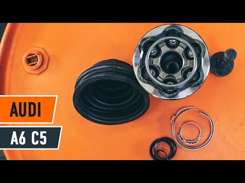
How to change cv joint on AUDI A6 C5 Avant
Other AUDI procedures
- Removing and installing toothed belt – Audi · 56 torque figures
- Removing engine – Audi A8 D3 · 41 torque figures
- Removing camshaft timing chain from camshafts – Audi A6/A7 C7 · 38 torque figures
- Installing engine – Audi A8 D4 · 36 torque figures
- Removing and installing camshaft timing chain · 29 torque figures
- Removing and installing water pump V36
- Checking vacuum hose to position sender for charge pressure positioner G581
- Removing and installing left side panel trim
- Removing and installing rear right side panel trim
- Removing and installing turbocharger (engine codes CEBA, CEBB, CECA, CECB)
Who makes these pages, and how
TorqFix was built by a mechanic — after a 2,700 km drive with five roadside repairs that no diagnostic tool could explain.
The figures on this page come from manufacturer workshop documentation and are shown as they are. The page is assembled automatically from that data — it is not written by an AI. The AI works in the chat, where it answers for your specific car. It writes nothing here.
Variants of the same model differ. Cross-check torque against the factory manual for your engine before final tightening.
Seen a figure that does not match your manual? Write to us — we correct it and note when. support@torqfix.com
The story behind TorqFix →Workshop data on this page last updated 20 Sep 2026.