
Servicing drive shaft with 100 mm ∅ outer constant velocity joint — AUDI
Servicing drive shaft with 100 mm ∅ outer constant velocity joint on Audi: 61 steps. What to remove, in what order, and what to check after.
Workshop procedure for AUDI — the exact step sequence and torque figures, straight from real workshop data.
🧭 Before you start
Fits: Audi A8 D3 (4E, 2002–2010)
- Special tools named: torque wrench
Don't miss
- Do not open hose clip.
- Apply clamp tensionerV.A.G 1682 as shown. Ensure jaws of clamp tensioner make contact with both sides of lug (arrows B) on hose clip.
- Ball hub and joint body are paired and must be marked before dismantling. Ensure that the balls run in the same races after assembly.
- Excessive backlash in the joint will cause knocking or jolts under load change. In such cases the joint must be renewed. Polished areas and visible tracks in the ball races are not a reason for renewing the joint.
- Swivel the hub into the joint body; at the same time the hub must be swivelled out of the cage (arrows) far enough to allow the balls to fit into the ball races.
📋 Procedure
- Clamp drive shaft in vice using protective jaw covers.
- Pry off cover using a screwdriver or similar.
- Remove gasket (arrow).
- Use brass or copper drift to drive off cap of boot. [Note: Do not open hose clip.]
- Remove circlip.
- Press inner constant velocity joint off drive shaft using special tools shown in illustration.
- Unfasten small hose clip on drive shaft and pull boot off drive shaft.
- Apply sealant (hatched area) to clean surface on inside of boot cover. Route continuous bead of sealant (2..3 mm ∅) around inside of holes (arrow).
- Use sealantETKA - Electronic parts catalogue.
- Push boot with small hose clip onto drive shaft.
- Grease splines (A) on drive shaft lightly with grease used in joint before fitting joint onto drive shaft.
- Press on joint as far as stop.
- Fit circlip.
- Check that circlip is properly seated.
- Before fitting cover, apply 60 g of drive shaft grease to constant velocity joint through ball tracks.
- Align cover and bolts (arrows) with bolt holes.
- Drive on cover using a plastic hammer.
- Wipe off surplus sealant.
- Pack 60 g of drive shaft grease into joint through ball races.
- Degrease contact surface for seal.
- Remove adhesive foil from gasket and glue into constant velocity joint.
- Align new cover (A) with bolt holes.
- Use special tools shown to press on cover (A).
- Position boot in outer groove (arrow 2).
- Apply clamp tensionerV.A.G 1682 as shown. Ensure jaws of clamp tensioner make contact with both sides of lug (arrows B) on hose clip.
- Tighten clip by turning spindle with torque wrench (C) (take care to keep tool straight). [Note: Ball hub and joint body are paired and must be marked before dismantling. Ensure that the balls run in the same races after assembly.]
- Swivel ball hub and ball cage.
- Push out joint body in direction of arrow.
- Push balls out of cage.
- Align ball hub with cage as shown (arrows) and pivot hub out of cage.
- Check joint, ball hub, ball cage and balls for pitting and signs of seizure. [Note: Excessive backlash in the joint will cause knocking or jolts under load change. In such cases the joint must be renewed. Polished areas and visible tracks in the ball races are not a reason for renewing the joint.]
- Insert hub into cage via the two chamfers. No specific installation position is required. Push balls into cage.
- Insert hub with cage and balls at a right angle to the joint body.
- Swivel the hub into the joint body; at the same time the hub must be swivelled out of the cage (arrows) far enough to allow the balls to fit into the ball races.
- Swivel in the hub with balls by applying firm pressure on the cage (arrow).
- Pack required amount of grease into joint body.
- Clamp drive shaft in vice using protective jaw covers.
- Use pliers3340 to unfasten hose clip.
- Push back boot.
- Use hammer to tap copper or brass drift (A) against inner race of constant velocity joint.
- Detach joint and boot.
- Push joint boot onto drive shaft.
- Position boot between (arrows).
- Pack 70 g of drive shaft grease inside joint body.
- Screw old drive shaft bolt into joint body as shown.
- Use plastic-headed hammer to drive joint onto shaft until circlip engages.
- Pack 50 g of drive shaft grease into joint (boot side).
- Fit hose clip on outer joint.
- Vent air from boot.
- Engage hose clip by hand at first lug.
- Use pliers3340 to fasten hose clip.
- Before dismantling, mark position of ball hub in relation to ball cage and joint body with an electric scriber or oil stone.
- Swivel ball hub and ball cage.
- Take out balls one after the other.
- Turn the cage until the two rectangular openings (arrow) are level with the joint body.
- Lift out cage together with hub.
- Swivel segment of hub with short lobe into square cage opening.
- Pivot hub out of cage.
- Fit cage with hub into joint body. [Note: Make sure cage is inserted in correct position (i.e. sides facing in same direction as original position).]
- Press in balls one after the other from opposite sides, taking care to re-establish original position of hub relative to cage and joint body.
Ask TorqFix about your Audi — it answers with the exact sequence for that engine. First question is free after a 20-second sign-up, no card.
Ask about your Audi — free → or sign up free to see the drawings🎬 Related video tutorial
Independent AUTODOC tutorial for the same job, filmed on a different model (A6 C5 Avant) — the technique carries over, the fasteners and figures on this page are the ones for your car.
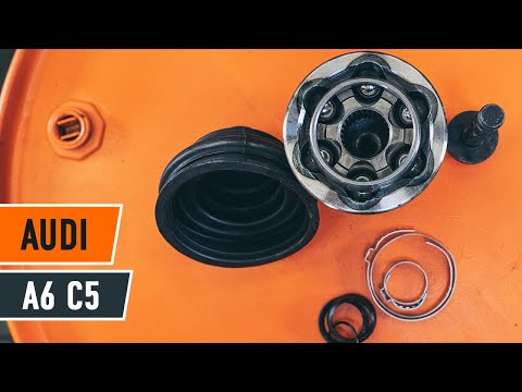
How to change cv joint on AUDI A6 C5 Avant
Other AUDI procedures
- Removing and installing toothed belt – Audi · 56 torque figures
- Removing engine – Audi A8 D3 · 41 torque figures
- Removing camshaft timing chain from camshafts – Audi A6/A7 C7 · 38 torque figures
- Installing engine – Audi A8 D4 · 36 torque figures
- Removing and installing camshaft timing chain · 29 torque figures
- Removing and installing toothed belt - vehicles from approx. 06.2005 onwards · 3 torque figures
- Removing and installing emission control module – Audi A3 · 3 torque figures
- Installing gearbox - vehicles with 6-cylinder engine – Audi · 3 torque figures
- 5-speed manual gearbox 012, 01W, 0A9, front-wheel drive — Renewing gearbox cover (with gearbox installed) · 3 torque figures
- Audi CCGA gearbox removal & installation · 3 torque figures
Who makes these pages, and how
TorqFix was built by a mechanic — after a 2,700 km drive with five roadside repairs that no diagnostic tool could explain.
The figures on this page come from manufacturer workshop documentation and are shown as they are. The page is assembled automatically from that data — it is not written by an AI. The AI works in the chat, where it answers for your specific car. It writes nothing here.
Variants of the same model differ. Cross-check torque against the factory manual for your engine before final tightening.
Seen a figure that does not match your manual? Write to us — we correct it and note when. support@torqfix.com
The story behind TorqFix →Workshop data on this page last updated 20 Sep 2026.