
Removing and installing brake pad wear sender — AUDI
Removing and installing brake pad wear sender on Audi: 12 steps. What to remove, in what order, and what to check after.
Workshop procedure for AUDI — the exact step sequence and torque figures, straight from real workshop data.
🧭 Before you start
Fits: platform code 42
Don't miss
- Make sure the contacts for the pad wear sender are properly seated in the brake pads.
📋 Procedure
- Remove corresponding rear wheel; on vehicles with ceramic brakes, observe precautions regarding ceramic brakes Running gear, front-wheel drive and four-wheel drive44Wheels and tyres.
- Unplug electrical connector (2) for pad wear sender.
- Release electrical connector (1) for pad wear sender from bracket (arrow B) and at the same time turn 90° (arrow A).
- Remove bolt (4) and push bracket (3) to one side.
- Unclip electrical wire for pad wear sender at pad retaining spring (arrow).
- Detach contacts (1 and 2) of pad wear sender from brake pads using pliers.
- Insert contacts (1 and 2) of pad wear sender into brake pads so that they engage. [Note: Make sure the contacts for the pad wear sender are properly seated in the brake pads.]
- Secure electrical wire for pad wear sender; to do so, attach it at retainer (arrow) as shown in illustration.
- Guide electrical wire (6) for brake pad wear sender towards rear, as shown in illustration, and tighten bolt (5) for bracket (4)
- Locate electrical connector in installation position and turn in direction of (arrow) until tab (1) engages in hole (3) in bracket.
- Plug in electrical connector (2).
- Fit rear wheel; on vehicles with ceramic brakes, observe precautions regarding ceramic brakes Running gear, front-wheel drive and four-wheel drive44Wheels and tyres.
🎬 Related video tutorial
Independent AUTODOC tutorial for the same job, filmed on a different model (A4 B8 Saloon) — the technique carries over, the fasteners and figures on this page are the ones for your car.
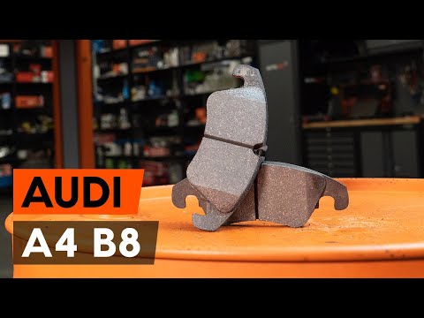
How to change front brake pads / brake pad set on Audi A4 B8 Saloon
Other AUDI procedures
- Removing and installing toothed belt – Audi · 56 torque figures
- Removing engine – Audi A8 D3 · 41 torque figures
- Removing camshaft timing chain from camshafts – Audi A6/A7 C7 · 38 torque figures
- Installing engine – Audi A8 D4 · 36 torque figures
- Removing and installing camshaft timing chain · 29 torque figures
- Gearbox adaption
- Exploded view - poly V-belt drive, vehicles up to model year 2013
- Checking fuel gauge sender 2 G169 - A5 up to model year 2011, A4 up to model year 2012, rest-of-world vehicles with four-wheel drive, USA vehicles with front-wheel drive/four-wheel drive
- Checking fuel gauge sender 2 G169 - A5 from model year 2012 onwards, A4 from model year 2013 onwards, rest-of-world vehicles with four-wheel drive, USA vehicles with front-wheel drive/four-wheel drive
- Removing and installing fresh air blower V2 (with J126 control unit)
Who makes these pages, and how
TorqFix was built by a mechanic — after a 2,700 km drive with five roadside repairs that no diagnostic tool could explain.
The figures on this page come from manufacturer workshop documentation and are shown as they are. The page is assembled automatically from that data — it is not written by an AI. The AI works in the chat, where it answers for your specific car. It writes nothing here.
Variants of the same model differ. Cross-check torque against the factory manual for your engine before final tightening.
Seen a figure that does not match your manual? Write to us — we correct it and note when. support@torqfix.com
The story behind TorqFix →Workshop data on this page last updated 20 Sep 2026.